English

News
Home / News / Industry News / How to Fix a Leaking Boiler: Causes, Diagnosis, Repair Steps in Plants

+86-13961025664
Content
A puddle under the casing of an industrial boiler is rarely just a plumbing problem. On a 60 t/h coke oven flue gas waste heat boiler, water appearing along a casing seam usually points to one of three things: a failed tube-to-tubesheet weld, a thinned economizer tube, or a weeping handhole gasket. Those three faults look almost identical from the walkway, and they cost wildly different amounts of money and downtime to put right.
The temptation is always the same: tighten something, keep the unit online, and deal with it during the next planned outage. That is exactly how a four-hour fix leaking boiler job turns into a three-week replacement project with a production penalty attached.
So here is the conclusion first. Stop, isolate and locate before anyone touches a wrench. In industrial boilers and waste heat boilers, roughly two thirds of water-side leaks come from a small, predictable set of locations, and each location has a preferred repair method with its own tolerance for delay. What follows covers what causes leaks, how to diagnose them safely, how the repair options compare on time and cost, and which material and design choices keep a boiler dry for the next decade.
Locate the leak source before opening a single tool box — the repair method is determined by the failure mechanism, not by where the water happens to drip.
Boiler leaks are not random. They cluster around a limited number of mechanisms, and each mechanism leaves its own signature on the metal. If you can name the mechanism, you can predict the repair, the downtime and the likelihood of the leak returning in the same place within twelve months.
| Leak location | Most likely root cause | First field check | Preferred repair |
|---|---|---|---|
| Tube-to-tubesheet weld | Cyclic thermal expansion, restrained weld toe | Dye penetrant test, boroscope of the joint | Local weld repair plus stress relief |
| Economizer or air preheater tube wall | Acid dew point corrosion, low feedwater pH | Ultrasonic wall thickness survey | Section retube with a corrosion-resistant design |
| Fire-side tube surface near soot blower | Ash erosion, steam cutting | Visual inspection during the outage | Sleeve repair or single-tube replacement |
| Handhole and manhole gaskets | Aged gasket, uneven bolt torque, distorted seat | Low-pressure refill and joint observation | New gasket with a documented torque sequence |
| Flange and bolted connections | Bolt relaxation under thermal cycling | Thermal imaging while the unit is warm | Re-torque to specification, add spring washers |
| Expansion joints and casing | Differential movement beyond bellows travel | Visual measurement of travel and gap | Redesign the expansion element |
| Headers and blowdown piping | Creep, erosion-corrosion from wet steam | Hardness test, ultrasonic thickness mapping | Header or pipe segment replacement |
Two quick ways to narrow the list. First, ask when the leak appears. A leak that shows up only on cold start is a contraction-related joint problem; a leak that grows with load is usually corrosion or erosion driven by flow and temperature. Second, ask where the water comes out relative to the gas path. Water-side failures wet the outer casing and insulation, while fire-side tube failures often show up as white steam in the flue or as a rise in stack temperature before any water is visible.
Most boiler leaks are symptoms of a mismatch between real operating conditions and the material, expansion or water treatment design — not evidence that somebody welded badly ten years ago.
Repairing a leaking boiler starts long before the welding machine arrives. The sequence below is the one we recommend to plant maintenance teams, and it is designed to protect both the crew and the evidence that tells you what actually failed.
A note on hydrostatic testing: any test above design pressure must follow the applicable code and the boiler's own certified documentation, and on a waste heat boiler with gas-side ductwork attached, the gas path must be positively isolated and purged before water is introduced. Cutting that corner is the fastest way to turn a maintenance task into an incident.
The diagnostic sequence is not paperwork — the operating data and thickness map you collect in steps three and six decide whether the repair lasts one year or fifteen.
When maintenance records are sorted by location instead of by date, a pattern appears almost immediately. Boilers are engineered assemblies with a finite number of weak points, and those weak points behave consistently across very different industries. A coke oven battery, a sintering machine and a power station boiler run different flue gas chemistry and different load profiles, yet the distribution of their leaks is remarkably similar. Knowing the expected distribution changes how you stock spares, how you write the inspection route, and how you brief the maintenance crew before an outage. The chart below shows a representative distribution of reported leak locations from industrial boiler and waste heat boiler inspections; individual plants will differ with fuel, water treatment and duty cycle.
Reported leak locations across industrial boiler inspections (illustrative distribution, percentage of all recorded leaks)
The first thing the chart says is that roughly a third of all leaks sit at the tube-to-tubesheet joint, which is the one place in a boiler where three different materials with three different expansion rates are welded into a single restrained connection. That concentration is not a manufacturing defect; it is the natural consequence of putting a cyclic thermal load on a stiff joint.
The second cluster, at twenty-six percent, covers economizer and air preheater tubes. These components live at the cold end of the gas path where metal surface temperature drops below the acid dew point, so a boiler that fires sulfur-bearing fuel and runs a low exit gas temperature will always lose its economizer first. If your plant has replaced economizer tubes twice in five years, the problem is the surface temperature margin, not the tube supplier.
The third group, gaskets, handholes and flanges at seventeen percent, is the most frustrating because it is almost entirely avoidable. These leaks come from aged elastomer, uneven bolt torque, distorted seats and joints retightened by feel rather than by specification. They are cheap to fix individually and expensive in aggregate, because each one costs an isolation, a cooldown and a restart.
Fire-side erosion near soot blowers accounts for twelve percent. The pattern here is highly localized: erosion follows the steam jet path, so the damaged tubes are usually the same three or four rows every time. Rotating soot blower positions or adjusting the blowing sequence between outages typically reduces this number substantially.
Expansion joints and casing account for seven percent, and headers and blowdown piping for four percent. Those are the low-frequency, high-consequence failures. A leaking expansion joint damages insulation and casing but rarely threatens the pressure boundary, whereas creep cracking in a header can be a forced-outage event with a long lead time for a replacement forging.
Read together, the distribution supports a simple maintenance strategy. Put the majority of your inspection budget into the tube-to-tubesheet joints, the economizer banks and the bolted joints, because those three areas carry seventy-seven percent of the risk. Use the remaining effort for thickness mapping on headers and pipework, where failures are rare but severe.
It also explains why generic advice about fixing leaking boilers so often disappoints. A plant that spends its outage on casing repairs while its economizer inlet temperature stays below the dew point will be back at work within eighteen months. The distribution tells you where to look first, and the operating data tells you why the leak chose that spot.
Three areas — tube-to-tubesheet joints, cold-end tube banks and bolted connections — carry more than three quarters of all boiler leak risk, so they deserve the majority of every inspection budget.
Once the mechanism is known, the repair options narrow quickly. The comparison below is written from the perspective of an operating plant that has to choose between a two-day repair and a six-week replacement, and it assumes the boiler code and the manufacturer's documentation are being followed.
| Method | Best suited to | Typical downtime | Relative cost | Realistic service life |
|---|---|---|---|---|
| Local weld repair | Isolated weld-toe crack, small pit on a thick pressure part | 1 to 3 days | Low | 3 to 10 years if the cause is corrected |
| Tube plugging | Individual failed tubes, up to roughly ten percent of a bank | 1 to 2 days | Low | Indefinite, but capacity and flow balance are reduced |
| Sleeving | Erosion or corrosion damage over a short tube length | 2 to 4 days | Low to medium | 2 to 6 years |
| Section retube | Multiple failures concentrated in one bank | 1 to 3 weeks | Medium | 8 to 15 years |
| Complete tube bundle replacement | Widespread wall loss or a change of duty | 3 to 6 weeks | Medium to high | 15 years or more |
| Full unit replacement | Shell, drum or header damage; duty no longer matches design | 2 to 6 months including fabrication | High | 20 years or more |
Three practical rules sit behind that table. First, plugging is a stabilisation measure, not a solution. Every plugged tube reduces heat transfer area and raises the flue gas exit temperature, which in turn pushes the remaining tubes closer to their dew point. Plug more than about ten percent of a bank and you have effectively redesigned the boiler without doing the engineering.
Second, welding repairs only last when the restraint that caused the original crack is addressed. On a tube-to-tubesheet joint, that means checking the expansion allowance, the tube-to-hole clearance and the heat treatment after welding. A repair that ignores those three items will crack at the same toe, usually within a year.
Third, the economics of repair should be judged on delivered heat, not on repair invoice. A leaking economizer that is plugged instead of retubed raises flue gas exit temperature, which raises fuel consumption every hour the boiler runs. On a unit firing continuously, that penalty can exceed the cost of a proper retube within two or three operating seasons.
Plugging and welding buy time; only a repair that removes the mechanical or chemical cause of the leak buys reliability.
When repair stops making sense, the replacement decision is driven by where the boiler sits in the process. Waste heat boilers are not interchangeable products; each configuration is matched to a gas source, a dust loading and a temperature profile. The strip below lists the configurations most often specified in coal chemical, metallurgy, power and ammonia plants.
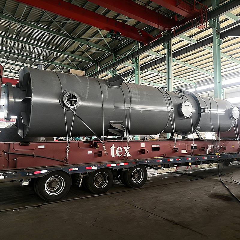
 Coke Oven Flue Gas Waste Heat BoilerThe Coke Oven Flue Gas Waste Heat Boiler is a high-efficiency, energy-saving device specifically developed for the coking industry. It aims to recover and utilize the ...View Product →
For each of these positions, ask the same four questions before requesting quotations. What is the design gas flow and temperature range at the inlet, including upset conditions? What is the dust loading and particle size distribution at the inlet? What is the sulfur and moisture content, and therefore the acid dew point that sets the minimum metal temperature? And what turndown does the plant actually operate at, as distinct from the nameplate range?
Supplier selection matters as much as configuration. A waste heat boiler is a pressure vessel with a gas-side heat transfer surface, so the manufacturer needs both a boiler and pressure vessel qualification and practical experience with the specific dust and corrosion environment. A supplier who has only built clean-gas heat exchangers will typically under-specify tube spacing and soot blowing, and the first leak will appear in the second operating year.
Match the boiler configuration to the process position, the dust loading and the acid dew point before comparing prices — configuration errors cannot be corrected by a discount.
Most of the leak prevention in an industrial boiler happens at the drawing stage, not in the maintenance shop. Three design decisions do most of the work: keeping metal temperature above the acid dew point, choosing a joint design that tolerates differential expansion, and limiting gas velocity in the first tube rows.
Dew point corrosion is the dominant mechanism in economizers and air preheaters. The engineering answer is a documented margin between the minimum metal temperature and the calculated acid dew point, sustained across the whole operating range including low-load conditions. A boiler that maintains this margin at full load but drops below it at forty percent load will still fail, just more slowly.
Where conventional welded economizer joints struggle with high temperature, high dust and corrosive condensate, brazed constructions offer a different set of trade-offs. A nickel-based brazed economizer uses a fully brazed tube-to-header connection, which removes the long weld toe that acts as a crack initiator on cyclically loaded joints and provides a more uniform contact between tube and fin. The filler metal is selected for corrosion resistance rather than for ease of welding, and the resulting surface resists the acidic condensate that attacks the cold end of a flue gas path.
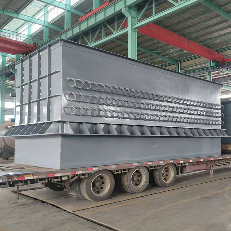
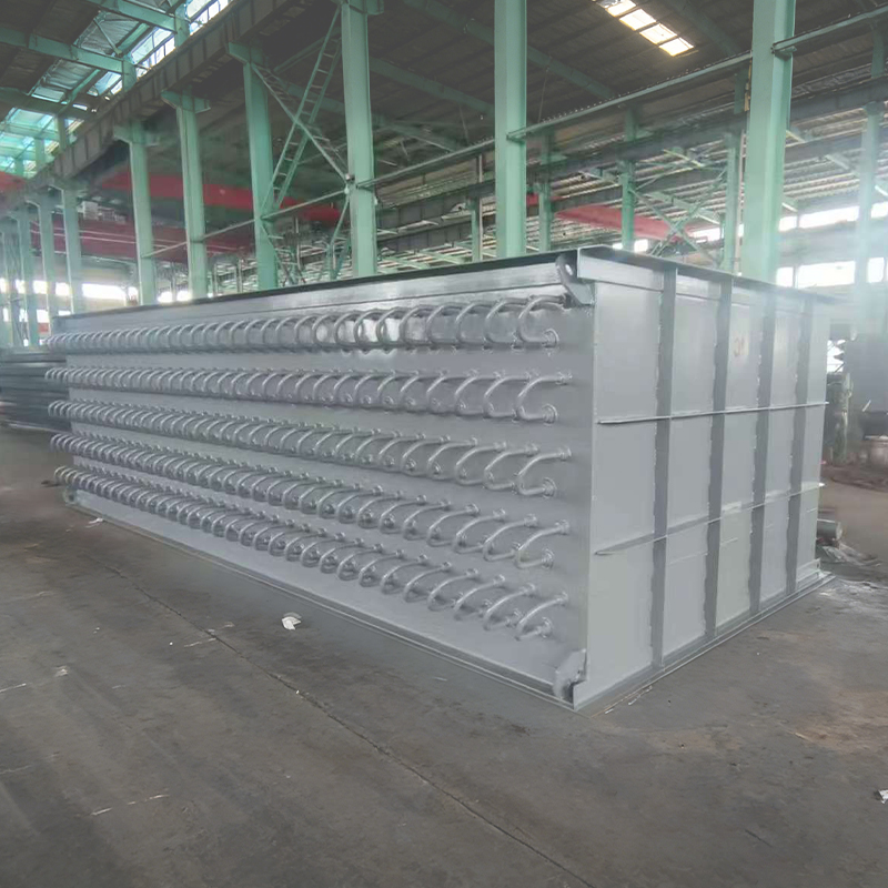 Nickel-based Brazed EconomizerNickel-based Brazed Economizers are advanced devices that significantly improve the economizer's corrosion resistance, wear resistance, ash accumulation resistance, an...View Product →
Where the requirement is simply to heat combustion air with residual flue gas heat, an air preheater is the more economical choice, provided the cold-end temperature margin is maintained and the gas-side passages can be cleaned without dismantling the whole bank. Selection between the two should follow the flue gas analysis, not the equipment catalogue order.
Erosion scales roughly with the cube of gas velocity, so the first rows of a dusty boiler should be designed for a lower velocity than the rest of the bundle. Soot blower placement matters too: a blower that directs steam at the same tube row from the same angle for years will erode a predictable line of tubes, and rotating the sequence between outages is a low-cost way to spread the wear.
On the water side, the design details that prevent leaks are less glamorous but equally decisive: correct drum internals to avoid steam carryover, adequate blowdown capacity to control dissolved solids, and a deaerator that genuinely removes oxygen rather than one that is merely present on the flowsheet. Water chemistry problems show up on the tube surface months later, and by then the damage is already localised pitting.
A documented cold-end temperature margin and a joint design that tolerates differential expansion prevent more leaks than any maintenance regime can repair.
The decision should be made against four numbers: measured wall thickness versus the minimum required, the number of leaks in the current operating period compared with the previous one, the remaining design life of the pressure parts, and the value of one day of lost production. When those numbers point in different directions, use the criteria below.
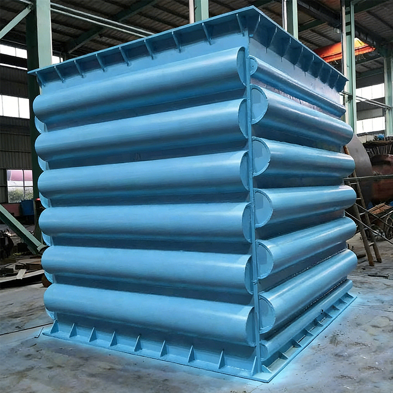
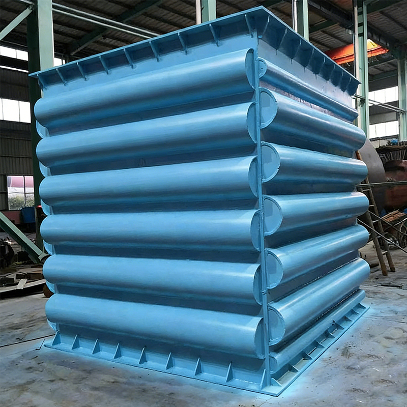
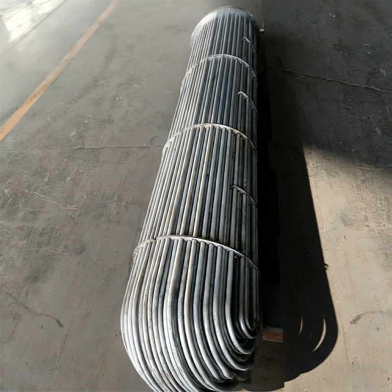 Shell and Tube Heat ExchangerThe Shell and Tube Heat Exchanger is a typical and universal industrial heat exchanger. Its core structure consists of a large shell (shell side) that houses the tube ...View Product →
| Repair in place when | Plan replacement when |
|---|---|
|
|
The payback calculation is worth doing properly. A leaking economizer that forces the plant to bypass part of the heat transfer surface raises the flue gas exit temperature, and every degree of lost recovery translates into additional fuel per hour. Multiply that hourly penalty by annual operating hours, add the cost of the unplanned outages the current unit has caused, and compare the total with the delivered price of a replacement bank including installation.
On many continuous-duty units the arithmetic resolves in favour of replacement within two to three years, and that is before accounting for the risk of a forced outage during a peak production period. On units that run a few weeks per year, by contrast, an in-place repair with correct water chemistry can remain the rational choice for a decade.
One further variable deserves mention: the cost of a poor-quality repair. A weld that passes a hydrostatic test but leaves a stress concentration at the toe will fail again, and the second failure usually costs more than the first because it arrives without warning and often during a production campaign.
Replace when leak frequency is rising across multiple banks and wall thickness is at the code minimum; repair only when the mechanism is known and the remaining life covers the next outage cycle.
A repaired boiler stays repaired only if the three drivers of leak formation are held inside their design envelope. Water chemistry controls the rate of wall loss from the inside, load cycling controls the accumulation of fatigue damage at joints, and inspection intervals decide whether the next leak is found by a technician or by a shift operator in the middle of the night.
| Interval | Activity | Record | Leak mechanism addressed |
|---|---|---|---|
| Every shift | Check drum level stability, blowdown operation and any visible seepage | Log readings and observations | Operating excursions, gasket weeping |
| Daily | Feedwater pH, conductivity and dissolved oxygen tests | Trend chart, not just a value | Water-side pitting and under-deposit corrosion |
| Weekly | Flue gas exit temperature and stack opacity check | Temperature against load baseline | Early tube leak, fouling and bypass |
| Monthly | Thermal imaging of casings, flanges and manhole doors while warm | Images filed against previous months | Joint and gasket leaks before failure |
| Annual outage | Ultrasonic thickness mapping of economizer and air preheater banks | Grid-mapped readings | Wall thinning from corrosion and erosion |
| Annual outage | Dye penetrant or magnetic particle testing of tube-to-tubesheet welds | Joint-by-joint records | Fatigue cracking at restrained joints |
| Every 3 to 5 years | Full pressure part inspection, header hardness testing, expansion joint travel measurement | Certified inspection report | Creep, expansion overtravel, casing damage |
Two habits make these intervals effective. The first is comparing readings against a load-corrected baseline rather than against a fixed alarm value, because most leaks announce themselves as a small trend change long before they cross a threshold. The second is writing the water chemistry correction into the same work order as the mechanical repair, so the fix and the cause are closed out together.
Load cycling deserves specific attention. Every startup and shutdown applies a full thermal cycle to the tube-to-tubesheet joints, the headers and the expansion elements, and fatigue damage accumulates regardless of how carefully the repair was executed. Reducing the number of unnecessary cycles, and holding ramp rates inside the manufacturer's curve, costs nothing and directly extends the interval between leaks.
Trend the chemistry and the exit gas temperature weekly — a leaking boiler almost always shows up as a trend change weeks before it shows up as water on the floor.
Once the decision moves from repair to replacement, the sourcing question becomes practical: who can deliver a pressure part that fits the existing ducts, meets the applicable boiler and pressure vessel requirements, and arrives inside the outage window? The answer is usually an original equipment manufacturer rather than a general fabrication shop, for three reasons.
The first is qualification. A waste heat boiler bank is a pressure boundary component, and the manufacturer needs the design and fabrication approvals that apply to your jurisdiction. In China that means a class three pressure vessel manufacturing licence for domestic work, and ASME stamping for exported equipment or internationally financed projects. A general steel fabricator cannot legitimately supply that part, however competitive the quotation looks.
The second is process knowledge. Gas-side heat transfer surfaces fail in specific ways in specific industries, and a manufacturer who has supplied coke oven, sintering and oxygen-blown applications will already know the erosion and fouling patterns. That experience shows up in tube spacing, soot blower placement, expansion joint travel and the cold-end temperature margin, all of which are invisible on a general arrangement drawing but decisive in service.
The third is delivery scope. A leak repair or replacement usually needs more than a bundle: it needs duct modifications, structural supports, insulation, refractory details, instrumentation tappings and commissioning support. Working with a single supplier who designs, manufactures, installs and commissions removes the interface risk between three or four separate contractors.
When evaluating potential suppliers, ask for evidence rather than claims: pressure vessel and boiler qualifications in writing, the in-house manufacturing equipment that determines the achievable joint quality, and a reference list from plants running comparable gas conditions. A manufacturer with its own brazing furnace, fin winding capacity and heat pipe production line has direct control over the joints that cause most cold-end leaks, which is a meaningful difference from a supplier who subcontracts those operations.
For plants operating internationally, the sourcing conversation should also confirm documentation practice: material certificates, welding procedure specifications and qualification records, non-destructive testing reports, hydrostatic test certificates and as-built drawings. Those documents are what an inspector will ask for, and their absence can delay commissioning long after the equipment has arrived on site.
Finally, price should be evaluated on a total-cost basis that includes the delivered heat recovery performance, the expected interval between maintenance interventions, and the supplier's response time for spares. A cheaper bundle that plugs the cold end with corrosion products within eighteen months is not cheaper at all.
Source pressure parts from a qualified boiler and pressure vessel manufacturer with in-house joint production — documentation and joint quality cannot be inspected into a subcontractor's work after delivery.
Across hundreds of inspection and repair jobs, the same five mistakes recur. Each one is inexpensive to avoid and expensive to repeat.
Each of these mistakes has a short-term logic behind it — time pressure, budget pressure, an outage window that is already slipping. The problem is that the cost of the mistake lands on the next maintenance budget, often during a production campaign when the plant can least afford an unplanned stop.
A simple discipline resolves most of them: before any repair is closed out, record the mechanism, the repair method, the measurement that justified it, and the operational change that will prevent a recurrence. Ten minutes of documentation at the end of a repair is the cheapest reliability investment available to a plant.
Every leak repair should close with a recorded mechanism and a corresponding operational change — otherwise the same leak is simply scheduled for a later date.
Two pages worth keeping open while a repair or replacement decision is being prepared:
Both pages assume the same starting point as this article: understand the mechanism, then choose the equipment.
Good sourcing decisions start with a clear failure mechanism — bring the gas analysis, the thickness map and the leak history to the first supplier conversation.
Fixing a leaking boiler is a decision sequence, not a single task. Identify the location, confirm the mechanism, choose a repair that removes the cause, and record the operating change that keeps it from returning. When the thickness data and the leak frequency say the unit is finished, treat replacement as an engineering project with a process position, a dust loading and an acid dew point attached, and specify the equipment against those numbers rather than against a catalogue page.
Plants that follow that sequence typically see fewer leaks, shorter outages and a longer interval between major interventions. Plants that chase the water instead of the mechanism see the same leak again, usually soon after the next restart, and usually at the least convenient moment of the production year. The difference between the two is not budget; it is the order in which the questions get asked.
Ask about the mechanism before the method, and about the design before the price — that order alone prevents most repeat boiler leaks.
We will help you move towards success.

Maqiao North High tech Industrial Agglomeration Zone, Jingjiang City, Taizhou City, Jiangsu Province

+86-18752676699 / +86-13961025664