English

News
Home / News / Industry News / Boiler PRV Leaking: Root Causes, Risks and Industrial Repair Practices

+86-13961025664
Content
At three in the morning, a warm puddle spreads across the floor under a boiler that was running perfectly the day before. The natural reaction is to assume the valve has failed and order a replacement. That reaction is usually wrong. A boiler PRV leaking is a symptom of pressure trouble somewhere else in the system, and the relief valve is simply the one component honest enough to report it.
A pressure relief valve, also called a PRV, safety valve or relief valve, is a mechanical device pinned to a fixed set point. Residential and light commercial hot water boilers commonly sit at 2.5 bar or 30 psi. Industrial units are set considerably higher depending on the pressure class and the applicable design code. The moment the sealing faces lift off the seat, even once, water, scale and suspended solids can be driven onto the seating surfaces. When the valve closes again, the faces no longer mate perfectly. That is when the dripping starts, first as an intermittent weep, then as a steady trickle that never quite stops.
The leak is therefore both a symptom and a consequence. As a symptom, it points at pressure control, thermal expansion or water make-up regulation. As a consequence, it means the valve itself has probably been damaged and will need replacement. Reverse that order and you get the pattern most plant and building engineers recognise: a new valve every heating season, and the same leak back within a few weeks.
The correct sequence is short. Read the system pressure gauge first. Test the expansion tank pre-charge second. Inspect the pressure reducing or auto-fill valve third. Only then pass judgement on the relief valve. Followed properly, that sequence resolves roughly three quarters of residential cases without touching the valve at all.
The stakes are higher on the industrial side. Waste heat boilers, economiser banks, air preheaters and shell and tube heat exchangers run continuously in high temperature, high dust and high corrosion flue gas conditions. Set pressure drift, thermal cycling and particulate deposition all accelerate seat degradation. Unplanned shutdown costs are measured in tens of thousands per day, while every litre lost through a weeping valve adds make-up water treatment cost, chemical consumption and downstream scaling risk on top of that.
Key takeaway: A leaking boiler PRV is first a pressure problem and only second a valve defect. Diagnose the system before replacing the component.
Across years of field service, a small number of recurring causes explain almost every boiler PRV leaking case encountered. Their diagnostic signatures differ, which is what makes them useful. Some leak cold, some leak only during a heating cycle, and some leak only while the make-up pump is running. Watching when and how often the leak appears narrows the field to one or two candidates before a single spanner is lifted. The distribution below comes from residential and light commercial hot water boiler service records, and several categories carry directly over to industrial waste heat boilers.
Waterlogged or failed expansion tanks account for roughly 34 percent and remain the single largest contributor by a wide margin. An expansion tank is a buffer, absorbing the volume that water gains as it heats. Once the diaphragm ruptures or the air charge disappears entirely, that buffer is gone and system pressure tracks straight into the relief valve set point on every firing cycle. Overfilled systems come second at about 24 percent, usually because a fill valve has stuck open or a pressure reducing valve outlet has drifted high, quietly pushing the system past its design pressure over hours or days. Thermal expansion and pressure control account for 18 percent and appear most often on small systems with no pressure sustaining control and no buffer volume.
Scale and seat damage make up around 15 percent. These cases usually have a history: the valve lifted once, debris lodged on the seating face, and the small weep that followed has now become a permanent leak. Spring fatigue and plain valve wear close the list at 9 percent, the smallest category but the easiest to confirm once the valve is off the line and bench tested. Taken together, the pattern is unambiguous. Roughly three quarters of leak events trace back to the system rather than to the valve. That is precisely why the direct replacement approach so often fails, because a new valve fitted onto a system with unresolved expansion control or make-up regulation simply repeats the same failure path.
On the industrial side the weighting shifts somewhat toward the valve itself. Continuous flue gas thermal shock, particulate deposition and elevated temperature ageing consume seating surfaces far faster than in a domestic system. Even so, on waste heat boilers and heat exchanger trains, checking system pressure, water side control logic and set pressure stability remains the fastest route to identifying what is actually behind a boiler PRV leaking problem.
A tank that is full of water instead of air offers no absorption at all. Pressure rises in direct proportion to temperature, the relief valve opens slightly on each cycle, and the seat degrades a little more each time. Testing pre-charge pressure with the system drained takes ten minutes and eliminates the single most common cause outright.
Auto-fill and pressure reducing valves drift. A valve set for 1.5 bar that has crept to 2.2 bar will slowly charge the system until the relief valve opens and discharges the excess. The leak then looks like a valve problem when it is really a fill control problem. Measure the outlet pressure of the fill assembly, not the boiler gauge, because they are often different.
Systems without a proper buffer, or with a cushion tank that has lost its air charge, see pressure rise with every burner cycle. The relationship is straightforward: a sealed volume of water expanding by one percent at 80 degrees Celsius generates a pressure rise far larger than most small systems can tolerate. Correct sizing of the expansion volume is the fix, not a stronger relief valve.
Once a valve discharges, hard water deposits bake onto the disc and seat. The result is a permanent weep that no amount of tightening will cure. On industrial equipment the same mechanism appears as sulphidation, oxidation and ash deposition on seating surfaces, which is why material selection matters as much as maintenance frequency.
Relief valve springs lose tension over thousands of thermal cycles. A valve rated at 1.6 MPa may begin lifting at 1.4 MPa after a few years, long before anyone notices. Periodic bench testing of set pressure is the only reliable way to catch this before it becomes a nuisance discharge.
Key takeaway: Expansion control and make-up regulation cause roughly three quarters of leaking PRV events. Fix the system, and the valve usually stops leaking on its own.
The physics of a leaking relief valve are identical whether the boiler heats a small building or recovers heat from a sinter strand. What changes is the operating envelope, the consequence of failure, and the engineering response. It is worth separating the two clearly, because guidance written for a domestic unit rarely transfers usefully to a pressure vessel operating at industrial scale.
Domestic and Light Commercial Boilers
|
Industrial Waste Heat Boilers
|
The consequences diverge sharply. A domestic leak might waste a few litres per day and stain a floor. An industrial leak on a waste heat boiler discharges treated, chemically conditioned water that has already consumed energy, chemicals and capital. Every cubic metre lost must be replaced, heated and treated again. Multiply that by continuous operation across a year and the cost is substantial even before any shutdown is considered.
There is also a compliance dimension. Industrial pressure equipment generally falls under a recognised design and fabrication code, with documented set pressure, capacity certification and periodic re-testing obligations. A valve that drifts out of specification is not just an annoyance; it is an inspection finding waiting to happen. For plant operators, keeping a documented history of set pressure verification is as important as keeping the valve itself clean.
Key takeaway: The same leak carries very different consequences at each scale. Industrial operators should treat set pressure drift as a scheduled maintenance item, not a reactive repair.
Working through the following sequence takes under an hour on a domestic system and half a shift on an industrial one. It consistently separates the valve from the system, which is the only decision that matters at this stage.
The tendency to skip step three is widespread and expensive. An expansion tank that reads correctly on a visual inspection can still be completely waterlogged, because there is no external sign until the air charge is measured directly. On industrial systems, step six is the equivalent blind spot, since set pressure verification is frequently deferred when production pressure is high.
Key takeaway: Never condemn a relief valve until the expansion volume, fill control and set pressure history have all been checked and cleared.
Replacement is a straightforward job when the surrounding conditions are right and a source of repeat failure when they are not. The list below covers the points that most often go wrong.
On industrial installations, an additional consideration applies. The discharge from a relief valve on a waste heat boiler carries high energy steam or hot water, and the discharge route must be engineered for it. Back pressure on the outlet side can shift the effective set pressure significantly, which is why outlet piping design receives as much attention as the valve selection itself during system integration.
Key takeaway: A correctly rated valve installed onto a blocked discharge line will leak just as badly as the one it replaced. Check the whole discharge path, not just the valve.
On a domestic boiler, a leaking relief valve drips onto the floor. On a waste heat boiler or an economiser bank upstream of the steam drum, it erodes the pressure boundary in ways that compound quietly: rising make-up water treatment cost, accelerating scale formation downstream, and a pressure envelope that drifts further from design every quarter.
The operating conditions bear no resemblance to a gas fired wall unit. Flue gas inlet temperatures commonly sit between 600 and 1000 degrees Celsius, often with significant dust loading and corrosive constituents. Thermal cycling is more severe, pressure swings more frequent, and opportunities for a valve to lift unnecessarily far more numerous. Set pressure drifts with time, seating surfaces foul, and springs lose tension under sustained heat. A valve set at 1.6 MPa two years ago may be lifting at 1.4 MPa now, with nobody aware of the change.
Drum design on coke oven and sinter waste heat boilers is matched to the waste heat recovery duty, which means water level control, blowdown philosophy and load response differ from a conventional power boiler. A relief valve with a drifting set pressure amplifies every one of those disturbances. Load swings, feedwater valve cavitation and steam water carryover all produce pressure spikes that a correctly set valve tolerates and a drifting one discharges on.
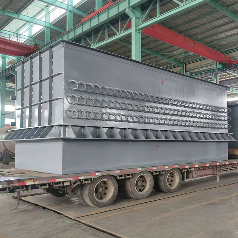
Upstream of the drum, the tail end heat recovery surfaces face the same problem from a different direction. Scaling or corrosion on an economiser raises flue gas side resistance, disturbs the water side flow distribution and pushes the pressure boundary into repeated excursions. A nickel based brazed economiser addresses this at the material level. The brazed construction resists oxidation and sulphuric acid dew point corrosion in high temperature, high dust flue gas, which keeps heat transfer stable and stops the pressure boundary from being hammered by avoidable transients. Fouling on the flue gas side almost always starts at the economiser, long before it becomes visible anywhere else.
Dust removal deserves equal attention in the same conversation. When flue gas reaches the heat exchange surfaces without adequate particulate removal, the fouling rate on every downstream component rises sharply. Air preheaters, economisers and shell and tube heat exchangers all lose performance faster, and the resulting pressure instability eventually finds its way to the relief valve. Positioning dust collection ahead of heat recovery is one of the least expensive forms of protection available for the pressure envelope.
Selecting equipment with the operating envelope in mind is the practical answer. Systems engineered around high temperature, high dust and high corrosion service, with material selection matched to the specific flue gas chemistry, cost more at the outset and considerably less over a fifteen year operating life. That calculation is worth revisiting whenever a relief valve becomes a recurring maintenance line item. Sinter and metallurgical waste heat boilers illustrate the same principle, where energy recovery performance and pressure stability are two outcomes of one design decision.
For engineers comparing options and payback periods, the relationship between heat recovery design and plant energy cost is well documented in the industry literature, and it is usually worth reviewing alongside any pressure boundary investigation.
Key takeaway: On industrial waste heat boilers, a leaking PRV is usually the visible end of a chain that begins with flue gas side fouling and drifting set pressure. Address the materials and the dust load, and the valve stops being a maintenance item.
Whether the job is a domestic replacement or a plant specification review, the same parameters decide whether the installation performs. The table below summarises what to confirm and where the common errors sit.
| Parameter | What to Confirm | Common Error |
|---|---|---|
| Set pressure | Matches the design pressure of the vessel or boiler with correct margin | Fitting a higher set pressure to stop nuisance discharge |
| Capacity | Rated relieving capacity exceeds maximum generating rate | Matching connection size only, ignoring capacity |
| Seat material | Suitable for the water chemistry and, on industrial units, the flue gas environment | Standard elastomer in high temperature service |
| Discharge piping | Free flowing, correctly supported, no back pressure build up | Shared discharge header creating back pressure |
| Expansion volume | Air charge verified at system cold fill pressure | Assuming a tank is good because it looks intact |
| Verification interval | Documented bench test of set pressure at fixed intervals | Testing only after a nuisance discharge occurs |
Two entries on that table cause more repeat failures than the rest combined. The first is set pressure substitution, where a stronger valve is fitted to silence a symptom that a system fix would have resolved properly. The second is unverified expansion volume, where an intact looking tank hides a failed diaphragm. Both are cheap to check and expensive to ignore.
On the industrial side, a third entry earns its place: verification interval. Thermal cycling degrades springs in a predictable way, and catching a five percent drift before it becomes a fifteen percent drift is the difference between a scheduled adjustment and an unplanned outage. Manufacturers and suppliers of pressure equipment generally publish recommended re-test intervals, and those recommendations exist for good reason.
Key takeaway: The two highest value checks in the entire maintenance programme are expansion tank air charge and documented set pressure verification. Everything else is secondary.
How long can a leaking boiler PRV be left in service?Not long, and the reason is not the water loss. Every day a valve weeps, dissolved solids deposit on the seating faces and the weep becomes a permanent leak. On a domestic system the practical window is days. On an industrial waste heat boiler, treat it as a defect with a defined rectification date rather than an observation to monitor. |
The valve was replaced and it still leaks. What was missed?Almost always the expansion volume or the fill control. A new valve fitted to a system whose expansion tank has lost its air charge will begin weeping within one heating cycle. Check the air pre-charge and the fill valve outlet pressure before concluding that the replacement valve is defective. |
What system pressure is actually too high?On a sealed hot water system, cold fill pressure should sit well below the relief valve set point, and hot operating pressure should stay below it with margin. A useful working rule is that normal operating pressure should not exceed about 80 percent of set pressure at any point in the cycle. If it does, the expansion volume is undersized or the fill control is passing. |
How often should industrial set pressure be verified?Follow the applicable code and the manufacturer recommendation, and shorten the interval where thermal cycling is severe. On high temperature waste heat service, annual verification is a reasonable starting point for many operators. Records matter as much as the test itself, because drift trends only become visible when results are compared over time. |
The valve still drips briefly after the fill pump stops. Is that normal?A short drip immediately after a discharge is normal as the disc reseats. Continued dripping beyond a minute or so is not, and points to debris on the seat or a distorted seating face. On industrial units, the same behaviour after a load transient usually indicates set pressure drift rather than contamination. |
Key takeaway: Most repeat failures trace to two root causes that were not checked the first time. Verify expansion volume and fill control pressure before condemning any replacement valve.
A boiler PRV leaking is one of the most misdiagnosed faults in steam and hot water plant. The valve is visible, accessible and cheap to swap, which makes it the default suspect even when the evidence points elsewhere. Working the sequence in the right order, pressure first, then expansion volume, then fill control, then the valve, resolves the vast majority of cases without a second visit.
On industrial installations, the same logic scales up with higher consequences. Waste heat boilers, economisers and air preheaters operating in high temperature, high dust and high corrosion service need set pressure verification built into the maintenance programme, and they need flue gas side fouling managed before it disturbs the water side. Material selection and dust removal upstream of the heat recovery surfaces are not optional refinements at that scale; they determine how often a relief valve becomes a maintenance line item.
For teams evaluating equipment or building a case for a waste heat recovery project, the following resources may be useful as a starting point.
As a waste heat recovery equipment manufacturer and supplier serving coal chemical, power, metallurgy and synthetic ammonia industries, the company designs, fabricates and commissions both individual pressure components and complete recovery systems, holding ASME boiler and pressure vessel accreditation alongside domestic Class III pressure vessel manufacturing licensing. For projects where pressure boundary reliability and heat recovery performance must both be delivered, that combination of fabrication qualification and system level engineering is worth evaluating early in the specification process.
Key takeaway: Diagnose the system, verify the set pressure, manage the flue gas side, and a leaking PRV stops being a recurring problem and becomes a scheduled maintenance task.
We will help you move towards success.

Maqiao North High tech Industrial Agglomeration Zone, Jingjiang City, Taizhou City, Jiangsu Province

+86-18752676699 / +86-13961025664
 Previous