English

News
Home / News / Industry News / Boiler Safety Relief Valve Leaking: Causes, Diagnosis and Fixes for Plants

+86-13961025664
Content
If a boiler safety relief valve is leaking, treat it as a defect on the pressure boundary, not as a housekeeping nuisance. The valve is the last mechanical barrier standing between a pressurised drum and an overpressure event, and a valve that passes steam continuously has already stopped being a dependable barrier. The visible plume is the end of a chain of events that usually started weeks earlier, when the first microscopic steam path opened between the disc and the seat.
The practical conclusion comes first, because it determines everything you do afterwards. Do not plug it, do not gag it, do not wire the lever down, and do not leave it isolated behind a closed upstream block valve. Isolate only long enough to plan a proper intervention, tag it, log the symptom, and then move straight to two parallel tracks: find out why it leaks, and confirm whether the valve can be re-certified or must be replaced.
There is a second conclusion that matters just as much. Most leaking relief valves are victims, not culprits. They leak because the set pressure margin is too thin, because the inlet pipe is undersized, because the spring has relaxed after years at elevated temperature, or because scale and dust from the flue gas path have collected on the seat. Replace the valve without correcting those conditions and the new one will leak on the same schedule.
This article walks through the sealing mechanism, the four different things plant teams call "leaking", the root causes ranked by how often they appear in cut-open valves, a step-by-step field diagnosis, the repair-or-replace decision, trim and material selection for high temperature and high dust flue gas, installation mistakes, inspection planning, and the procurement questions that prevent the problem from being designed into the next waste heat boiler.
A spring-loaded safety relief valve holds pressure with a surprisingly small contact area. The disc rests on the seat with a narrow, lapped band of metal-to-metal contact, loaded by a spring whose force has been calibrated to open at a specific pressure. Everything upstream of that contact band, and everything that keeps the disc aligned on it, belongs to the sealing chain. A leak appears when any single link in that chain drifts.
The chain has five links. The first is the disc and seat pair, which does the actual sealing. The second is the guide and stem, which keep the disc concentric with the seat so the load is evenly distributed. The third is the spring, which defines the set pressure and must stay within tolerance through thousands of thermal cycles. The fourth is the bonnet and, where fitted, the bellows, which isolate the spring from the process and manage the backpressure acting on the disc. The fifth is the inlet nozzle and body, which must deliver flow to the valve without an excessive pressure drop.
On a boiler or a waste heat boiler, the sealing chain is under continuous attack. Steam at 250 to 450 degrees Celsius causes differential expansion between the disc and the seat, both of which are usually made from different alloys or at least different section thicknesses. Every start-up and shutdown flexes the spring. Every hour at temperature relaxes it a little more. Dust, iron oxide and condensate salts travel with the flue gas and find the one place where the clearance is measured in microns.
This is why the failure is progressive rather than instantaneous. A seat that passes a few grams of steam per hour is already damaged. Superheated steam accelerates through a gap of a few microns at close to sonic velocity, and that jet erodes the seat face and the disc face within hours of the first pass. A leak that started as a whisper ends as a visible plume and a scored seat that must be replaced rather than lapped.
| Component | Role in sealing | How it contributes to leaks |
|---|---|---|
| Disc and seat | Primary metal-to-metal sealing band | Nicks, wire drawing, erosion grooves, thermal deformation, scale embedded in the contact band |
| Guide and stem | Keep the disc concentric and evenly loaded | Galling, corrosion products in the guide clearance, eccentric loading that opens one side of the seat |
| Spring | Defines set pressure and reseating force | Relaxation at temperature, corrosion pitting, wrong spring installed after a previous repair |
| Bonnet and bellows | Isolate the spring and balance backpressure | Bellows rupture, bonnet gasket leakage, steam weeping from the joint |
| Inlet nozzle and body | Deliver full flow with minimal pressure drop | Fouling, scale build-up, an inlet pipe smaller than the valve inlet, turbulence from a close elbow |
Plant teams use one word for four different physical conditions, and that is where diagnosis usually goes wrong. A valve that simmers just below set pressure is not in the same condition as a valve passing a visible plume at normal operating pressure, and neither of them is the same as a gasket weeping at the bonnet joint. Each signature has a different cause, a different urgency, and a different remedy.
Simmering is the mildest and the most commonly ignored. The valve begins to release a thin, high-pitched stream when the boiler approaches but does not reach set pressure. It is often audible before it is visible, which is why operators who work near the drum know about it long before maintenance does. Simmering is a warning that the margin between operating pressure and set pressure has become too small, or that the spring has relaxed enough to lower the effective popping point.
Seat leakage is a different animal. The valve passes steam at normal operating pressure, producing a visible plume or a continuous hiss that never stops. By the time this is noticed, the seat is almost always damaged and the damage is progressing quickly. Condensate weeping is subtler: during start-up, water collects on the seat and drips from the outlet, which looks alarming but often clears once the valve is at temperature.
Finally, joint leakage and failure to reseat after a manual lift test are separate events. A weeping bonnet gasket or outlet flange is a bolting or gasket problem, not a seat problem. A valve that stays open after the lift lever is released has a mechanical binding problem in the guide or stem. Confusing these four cases leads to unnecessary overhauls, or worse, to a genuine seat leak being dismissed as condensate.
| Signature | How it appears in the field | Most likely cause | Immediate action |
|---|---|---|---|
| Simmering | Faint high-pitched whistle just below set pressure, no visible steam | Operating pressure too close to set pressure, thermal creep of the disc, relaxed spring | Reduce operating pressure, log the pressure trend, plan an overhaul at the next opportunity |
| Seat leakage | Continuous visible plume or steady hiss at normal operating pressure | Debris or scale on the seat, seat face damage, wire drawing | Isolate, tag, and overhaul the valve; assume the seat needs work |
| Joint leakage | Steam weeping at the bonnet, the outlet flange or the body-bonnet joint | Gasket degradation, uneven bolt torque, thermal cycling of the joint | Retorque to specification when cool, or replace the gasket during the next shutdown |
| Failure to reseat | Valve remains open after the lift lever is released | Galling or dirt in the guide, bent stem, distorted disc | Isolate the valve, do not force the lever, and remove it for inspection |
Root cause data taken from plant maintenance records is never perfectly uniform, because different sites classify the same failure in different ways. Even so, the pattern that emerges when leaking valves are removed, cut open and photographed is consistent enough to be useful. Across coking, sintering, power, metallurgy and chemical plants, the same six explanations account for nearly every reported case. The distribution below is a composite of those failure classifications as they appear on inspection reports after the valve has been opened in a workshop. It is not a statistical study, and it should not be read as a fixed law. It is a triage order, a practical ranking of where the physical evidence most often points.
Foreign matter on the seat is the single largest category, and it is also the most preventable. In flue gas applications the debris is rarely a foreign object in the literal sense. It is iron oxide scale spalled from the superheater or economizer tubes, dust carried through a bypass, welding slag left in the drum during construction, or treatment chemical deposits that build up on the hottest surface in the steam space. Because the valve sits at the highest point of the drum or header, it collects whatever the steam carries. Once a particle is trapped between the disc and the seat, the valve cannot close on a full contact band, and the resulting jet finishes the job within hours.
Seat and disc face damage ranks second, and it is usually the consequence of the first category rather than an independent event. The cut-open valves show the characteristic erosion groove that runs radially across the seat face, often with a matching mark on the disc. Damage of this type cannot be lapped out in the field once it exceeds roughly half a millimetre of depth; the seat has to be remachined or the trim replaced.
Set pressure drift and spring relaxation come third, and this category is heavily over-represented in high temperature service. A spring that lives at 400 degrees Celsius for several years loses free length, and a shorter spring opens at a lower pressure. The valve then simmers, lifts earlier than the nameplate suggests, and wears its seat faster. This is why nameplate pressure and actual popping pressure can differ by five to ten percent on old valves that have never been re-certified.
Installation and backpressure problems account for a further significant share. An inlet pipe one size smaller than the valve inlet, a sharp elbow within a few diameters of the valve, or an outlet pipe that develops built-up backpressure above ten percent of set pressure will all produce chatter, and chatter destroys a seat faster than almost anything else. The valve lifts, slams shut, lifts again, and the repeated impact deforms the disc face.
Simmering and thermal creep sit in the middle of the list because they are usually a symptom of a thin pressure margin rather than an independent failure. When the boiler operating pressure is set at ninety-five percent of the relief valve set pressure, the valve is being asked to operate at the edge of its reseating ability, and the smallest amount of thermal distortion at the seat will produce a pass.
Incorrect sizing or wrong selection is the smallest category in absolute numbers but the most expensive to correct. A valve sized for a fire case that never occurs, or with a trim material selected for dry steam but installed in wet, corrosive service, will fail on a schedule that has nothing to do with maintenance quality. The lesson from the ranking is straightforward: three quarters of all leaks come from debris, seat condition and spring behaviour, and all three respond to a combination of correct set pressure margin, clean steam at the valve inlet, and a disciplined re-certification interval.
 Coke Oven Flue Gas Waste Heat BoilerThe Coke Oven Flue Gas Waste Heat Boiler is a high-efficiency, energy-saving device specifically developed for the coking industry. It aims to recover and utilize the ...View Product →
A conventional fired boiler produces steam at a comparatively stable rate, with a fuel input that can be trimmed and a drum pressure that follows a predictable curve. A waste heat boiler does not have that luxury. Its heat source is a process flue gas whose temperature, flow and dust loading are set by an upstream furnace, a sintering line, a coke oven battery or a converter, and none of those processes is adjusted for the convenience of the boiler.
That difference shows up directly at the relief valve. Rapid load changes produce pressure swings, and every swing brings the disc closer to its seat lift point. Thermal cycling of the drum and the superheater produces differential expansion that flexes the inlet nozzle. Coke oven flue gas carries tar, dust and sulphur compounds. Sintering gas carries fine iron-bearing dust that behaves like an abrasive. Oxygen-blown converter gas carries very high temperatures and intermittent operation. Each of these conditions attacks a different link in the sealing chain.
The dust problem is the most underrated. A waste heat boiler that is recovering heat from a dirty gas stream must protect the relief valve inlet from particulate carryover, usually by keeping the valve on the steam side of the drum where it belongs and by ensuring the steam separation equipment upstream is doing its job. When the steam purity degrades, the valve becomes the final filter in the system, and it pays for that role with its seat.
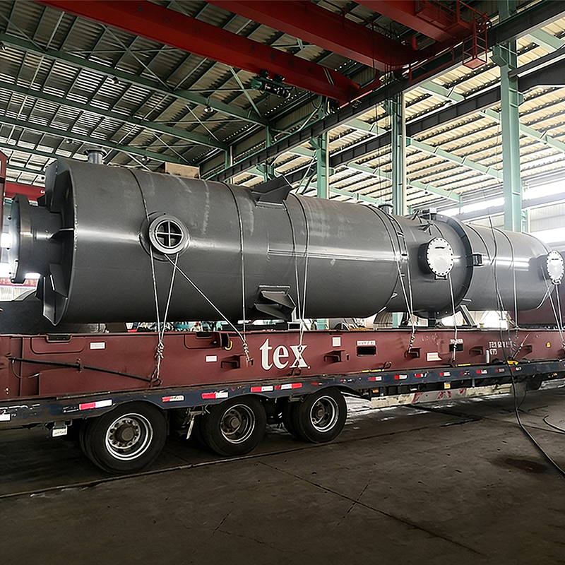
Companies that design and build industrial flue gas waste heat recovery equipment for coking, sintering, metallurgy and chemical plants work with these conditions every day. A coke oven flue gas waste heat boiler, for example, is designed around a specific gas composition, a specific dust loading and a specific load profile, and the relief valve specification has to be derived from those same parameters rather than copied from a standard steam drum. The same logic applies to the steam purity target, the drum internals and the blowdown arrangement, all of which ultimately determine how long the relief valve stays tight.
There is one more factor that is specific to waste heat boilers and frequently overlooked. Because the heat source keeps running even when the steam demand disappears, these boilers are often operated at low load with a wide pressure band, and the relief valve is asked to live through a much larger number of small pressure excursions than a base-load fired boiler. Fatigue at the seat contact band is therefore cumulative, and an inspection interval copied from a conventional boiler will be too long.
Diagnosis should follow a fixed order, because each step either eliminates a cause or points to the next measurement. Skipping ahead to the valve itself is the most common error: teams remove the valve, find a marked seat, lap it, reinstall it, and watch it leak again three weeks later because the real cause was an undersized inlet pipe or a backpressure problem on the outlet.
The measurements that matter are surprisingly few, and they can all be taken with standard workshop equipment. The trick is to take them in a fixed order and to write them down, because the pattern across two or three valves on the same plant usually reveals a system problem rather than three independent valve failures.
| Check | Method | Target | What a deviation indicates |
|---|---|---|---|
| Operating pressure versus set pressure | DCS trend compared with the nameplate | Operating pressure at or below 90 percent of set pressure | A thin margin that causes simmering and premature lift |
| Inlet pressure drop | Measure at the drum and at the valve inlet | No more than 3 percent of set pressure | Inlet pipe or nozzle undersized, causing chatter |
| Built-up backpressure | Calculate from the discharge pipe, or measure during a lift test | No more than 10 percent of set pressure | Outlet pipe too small or blocked, causing unstable lift |
| Body and bonnet temperature | Infrared thermometer or contact thermocouple | Within the rated trim temperature | Wrong trim material or an unexpected superheat condition |
| Seat tightness | Workshop test rig or hot pop test | No visible leakage at 90 percent of set pressure | Seat damage, embedded debris or distortion |
| Spring free length | Caliper measurement against the drawing | Within the manufacturer's tolerance | Relaxation from long-term elevated temperature service |
| Stem straightness and guide clearance | Dial gauge on a surface plate, visual inspection | Within the drawing specification | Binding that prevents full reseating after a lift |
The three most common conditions produce a leak that looks similar from a distance and behaves very differently up close. Simmering is a pressure margin problem. Seat damage is a mechanical problem. Set pressure drift is a calibration problem. The right repair for one is the wrong repair for the others, and a workshop that laps a seat without measuring the spring will return a valve that leaks again within a month.
The simplest way to separate them is to watch how the leak responds to a change in boiler pressure. A simmering valve goes quiet when the boiler pressure drops by a few percent, because the disc reseats as soon as the lifting force falls below the spring load. A valve with seat damage keeps passing steam at any pressure, because the contact band is no longer continuous. A valve with a drifted set point behaves normally for months and then opens far earlier than the nameplate suggests, often during a routine start-up.
| Characteristic | Simmering | Seat damage | Set pressure drift |
|---|---|---|---|
| When steam passes | Only when pressure approaches set point | At any pressure, including normal operating pressure | Suddenly, after a pressure event or a long interval |
| Sound | High-pitched whistle, intermittent | Steady hiss, sometimes a low roar | Normal pop sound, but at the wrong pressure |
| Response to lower boiler pressure | Leak stops | Leak continues | Not applicable until the next lift |
| Appearance on the seat | Light polishing, no groove | Radial erosion groove, matching disc mark | Seat often clean and undamaged |
| Spring condition | Usually within tolerance | Usually within tolerance | Free length below specification |
| Correct remedy | Widen the pressure margin, re-certify the valve | Remachine or replace the seat and disc, re-certify | Replace the spring, re-certify on a test rig |
A fourth condition deserves a mention because it is often misdiagnosed as seat damage. Debris or scale trapped on the seat produces a leak that appears suddenly, usually within hours of a start-up, a sootblowing cycle or a water chemistry upset. When the valve is removed, the seat face is often found almost intact under the deposit. Cleaning it, checking the spring and re-certifying the valve is usually enough, provided the upstream source of the debris is addressed.
Temperature is the diagnostic that ties all four together. A valve that is running hotter than its trim rating will creep, whether the trim is 13 percent chromium steel or a hardened alloy, and the creep shows up as a distorted disc or a seat that no longer matches the guide axis. If body temperature readings suggest the valve is regularly above its rated range, the correct response is a material change, not a more frequent re-certification interval.
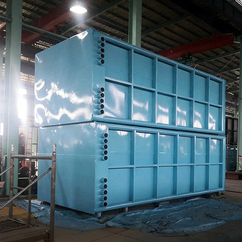 Sintering Waste Heat Boiler on Main Flue Gas DuctThe Sintering Waste Heat Boiler on Main Flue Gas Duct is an energy-saving device installed in the main flue at the tail end of the sintering machine to recover the was...View Product →
Once the valve is on the bench, the decision is usually about cost and lead time rather than about technical feasibility. Most seat damage can be repaired, most springs can be replaced, and most bodies can be re-certified, provided the original trim and capacity data are available. The hard cases are valves with no documentation, valves whose bodies show cracking or severe corrosion, and valves that have been modified in ways that cannot be verified.
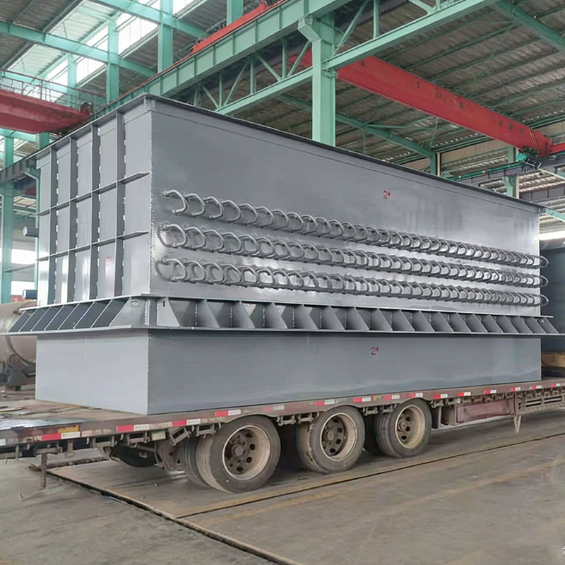
Lead time is the variable that catches most maintenance planners off guard. A routine lap and re-certification can be turned around in days at a qualified workshop. A full trim replacement with a new seat and disc usually takes one to three weeks. A brand-new valve with a specific trim, a bellows and a certified capacity test generally takes four to twelve weeks, and longer if the material is a nickel-based alloy. On a sintering line where the relief valve is the last barrier on a waste heat boiler recovering heat from the main flue gas duct, that lead time has to be planned rather than discovered during an outage.
There is also a compliance dimension that overrides cost in most jurisdictions. A safety relief valve on a boiler is part of the protected pressure boundary, and its capacity, set pressure and certification have to be traceable. A valve that has been repaired without a test record, or whose spring has been replaced with an unverified part, is not just a maintenance risk; it is a documentation problem that will surface during the next statutory inspection.
| Condition found | Recommended action | Typical lead time | Risk if deferred |
|---|---|---|---|
| Light polishing or a shallow mark under 0.5 mm | Lap the seat, replace gaskets, re-certify and tag | Several days | Leak returns within weeks if the upstream debris source is not corrected |
| Deep erosion groove or a scored disc face | Remachine or replace the seat and disc, re-certify | One to three weeks | Erosion accelerates and the body may become unrepairable |
| Spring free length out of tolerance or corroded | Replace the spring with a certified part, re-certify | One to two weeks | Early or late opening, loss of overpressure protection margin |
| Body or bonnet cracking, severe corrosion or unknown trim | Replace the valve with a documented equivalent | Four to twelve weeks | Loss of overpressure protection and a compliance finding |
| Valve over fifteen years old with no repair history | Replace with a fully documented new valve | Four to twelve weeks | Unknown capacity and set point, repeated emergency work |
Whatever the decision, one rule is worth keeping. When a plant keeps a spare valve on the shelf, the spare should be identical in set pressure, capacity and trim to the installed unit, and it should be re-certified on the same schedule as the installed valves. A spare that has been sitting in a warehouse for five years with an unknown spring is not a spare; it is a second problem waiting to be installed.
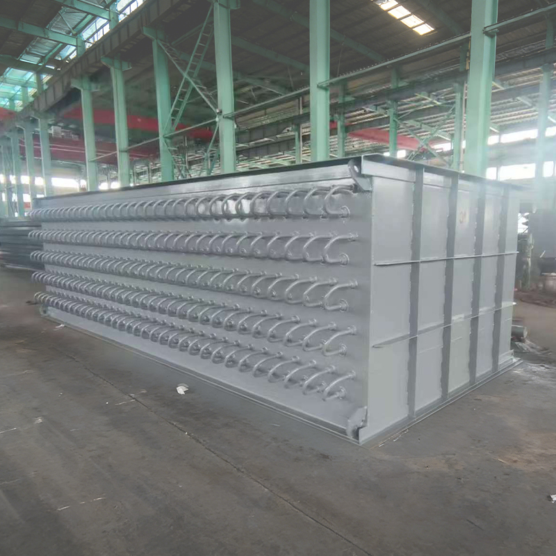 Nickel-based Brazed EconomizerNickel-based Brazed Economizers are advanced devices that significantly improve the economizer's corrosion resistance, wear resistance, ash accumulation resistance, an...View Product →
Material selection is where a relief valve problem becomes an engineering problem rather than a maintenance problem. A trim that is perfectly adequate for dry saturated steam at 200 degrees Celsius will creep, gall and leak in superheated steam at 400 degrees Celsius, and the same valve installed in a flue-gas-side environment will corrode at the guide and the spring chamber long before its seat wears out.
The temperature effect on springs is the least visible and the most underestimated. Spring relaxation is a slow creep process, and its rate roughly doubles for every fifteen to twenty degrees of additional temperature within the operating range of typical spring steels. A valve that runs twenty degrees hotter than the design assumption will lose its set point in a fraction of the expected service life, and it will do so quietly, without any visible sign until the popping pressure is measured.
Corrosion follows the same logic. Chlorides and sulphur compounds in coke oven gas and in some sintering gas streams attack stainless steel trim at the guide surfaces and at the seat contact band. Where condensate can form during start-up, wet steam carries those compounds directly to the seat. Once pitting begins at the seat band, the valve cannot close on a continuous contact line, and no amount of lapping will restore a surface that is being chemically attacked while the boiler runs.
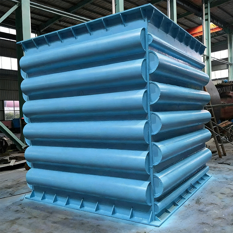
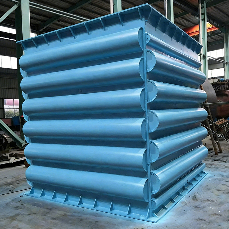
The same materials discipline that governs the pressure parts of a waste heat boiler governs its relief valve trim. Equipment such as a nickel-based brazed economizer is specified with a brazed, corrosion-resistant surface precisely because the flue gas path destroys cheaper materials at temperature. The relief valve on the same gas path deserves the same reasoning: choose the trim for the chemistry and the temperature, not for the purchase price.
| Service condition | Recommended trim | Notes |
|---|---|---|
| Dry saturated steam below 250 degrees Celsius | Standard 13 percent chromium stainless steel | Acceptable for most base-load waste heat boilers with clean steam |
| Steam above 250 degrees Celsius with thermal cycling | Hardened, cobalt-alloy faced disc and seat | Reduces galling and resists the wire-drawing that follows a small leak |
| Wet steam or condensate-prone service | Corrosion-resistant stainless trim with a hardened disc | Check the drum internals and steam purity before blaming the valve |
| Flue gas side or chemically aggressive environment | Nickel-based or high-nickel alloy trim | Chloride and sulphide attack at the guide is the usual failure mode |
| High dust upstream of the steam space | Standard trim with a bellows and a protected inlet | Prevents particulate from reaching the seat and the guide clearance |
A bellows deserves a specific comment, because it solves two problems at once. It isolates the spring and the bonnet from the process fluid, which protects the spring from corrosion and prevents the bonnet from becoming a low point where condensate collects. It also balances the effect of backpressure on the disc, which matters on any valve with a long discharge line. The trade-off is that a bellows can fail, and a failed bellows will release process fluid into the bonnet. A tell-tale connection on the bonnet is the standard way to detect that failure before it becomes a leak at the bonnet joint.
Many valves that are repaired perfectly still leak within months, and the reason is almost always in the piping rather than in the valve. Two numbers dominate the installation standard: inlet pressure drop should not exceed three percent of set pressure, and built-up backpressure should not exceed ten percent of set pressure. Those limits exist because a relief valve is designed to sense pressure at its inlet and to discharge into an atmosphere it can overcome, and both assumptions break down when the piping is wrong.
An inlet pipe one size smaller than the valve inlet is the classic error. It is chosen to save space on a crowded drum top, and it produces exactly the pressure drop that makes the valve chatter. Chatter means the disc lifts and slams repeatedly in rapid succession, which deforms the seat face and loosens the guide. A sharp elbow installed a few diameters upstream has a similar effect, because the turbulence it creates produces an uneven pressure distribution across the inlet nozzle.
On the outlet side, the errors are even more common because they are less visible. A discharge line with a pocket collects condensate, which sits on the seat and corrodes it. A long discharge header shared with other valves can develop backpressure well above the ten percent limit when several valves lift together. And an isolation valve installed upstream of the relief valve without a locked-open device is an invitation for someone to close it during a maintenance campaign and forget to reopen it.
| Mistake | Effect | Correction |
|---|---|---|
| Inlet pipe smaller than the valve inlet | Pressure drop above three percent, causing chatter | Increase the pipe one size above the valve inlet |
| Sharp elbow close to the valve inlet | Turbulence and uneven loading on the disc | Provide a straight run of several diameters before the valve |
| Outlet line with a pocket or no drain | Condensate collects and corrodes the seat | Drain at the lowest point of the discharge line |
| Shared discharge header with several valves | Excessive built-up backpressure during simultaneous lift | Size the header for the combined rated flow of all valves |
| Isolation valve without a lock-open device | Valve accidentally left isolated | Fit a locked-open valve or a rupture pin arrangement |
| Relief valve used as a pressure control device | Repeated lifting and rapid seat wear | Install a proper pressure control loop and let the relief valve stay closed |
| Discharge pipe supported from the valve body | Nozzle loads distort the body and the guide | Support the pipe independently of the valve |
One further installation point is worth a sentence because it is so often missed during retrofit work. When a waste heat boiler is added to an existing steam system, the relief valve set pressure is sometimes carried over from the old drum without re-checking it against the new maximum allowable working pressure and the new operating pressure band. The result is a valve that is technically correct for the old system and chronically simmering on the new one.
Relief valve condition does not deteriorate linearly, and that fact has a direct effect on inspection intervals. During the first months after an overhaul, the valve is in its best condition, the set pressure is within tolerance and the seat is freshly lapped. As time passes, three processes run in parallel: the spring creeps and loses free length, the seat contact band accumulates deposits, and the number of pressure excursions accumulates as fatigue at the contact line. None of these is visible from outside the valve, and all three are accelerated by dust, temperature and cycling.
The curves below represent that combined deterioration as a leakage severity index, from a clean and stable steam service at the low end to a high-temperature, high-corrosion, heavily cycled waste heat boiler service at the high end. The index is not a code requirement; it is a planning tool that shows why a single interval for every relief valve in a plant is always wrong in one direction or another. A valve on a clean base-load drum and a valve on a coke oven flue gas boiler should not share a maintenance calendar. The difference widens sharply after the first year, and by the second year the gap between the two services is large enough to change the whole inspection strategy. Read the chart as a comparison of relative risk, not as an absolute prediction.
The first observation from the chart is that all three services start close together. In the first three months, the difference between a clean steam drum and a coke oven flue gas boiler is almost invisible on the index, because a freshly lapped seat and a new spring behave well regardless of the environment around them. This is why a maintenance interval chosen right after an overhaul tends to look adequate, and why it is usually extended too far.
The second observation is where the curves separate. Between six and twelve months, the clean service is still comfortably below a third of the index, while the hot and corrosive service has already climbed above forty. The high dust service sits between them. This is the point at which most plants discover the leak, because it has become audible or visible.
The third observation is the shape of the dashed curve. It does not flatten out. Beyond eighteen months it approaches the top of the scale, which reflects the fact that seal damage, once started, feeds on itself. The steam jet erodes the seat, the eroded seat passes more steam, and the process accelerates. There is no natural recovery point, which means a deferred overhaul does not save work; it converts a lapping job into a trim replacement.
The fourth observation concerns the gap between the top and bottom curves at twenty-four months. It is more than fifty index points, which in practice is the difference between a valve that can be lapped and re-certified and a valve that needs a new seat and disc. A plant that applies one interval to both services will either waste money on unnecessary overhauls of clean-service valves or accept repeated failures on aggressive-service valves.
The fifth observation is about the effect of a single pressure excursion. The curves are smooth because they represent average behaviour across many valves, but individual valves show step changes after a water chemistry upset, a sootblowing campaign or a load swing. A valve that sits at twenty on the index can jump to forty in a single week. This is why the interval should be treated as a maximum and combined with an event-triggered inspection rule.
In practical terms, the chart supports three planning decisions. Set the interval from the service condition rather than from the calendar year. Treat any chemistry, load or start-up event as a trigger for an earlier inspection on the affected valves. And keep at least one fully certified spare that matches the aggressive-service valves, because those are the ones that will not give you the four to twelve weeks a new valve needs.
| Service condition | Inspection interval | Activity |
|---|---|---|
| Clean, stable steam service | Up to 24 months | Pop test, seat inspection, re-certify and re-tag |
| Cyclic waste heat boiler with clean gas | 12 months | Pop test, spring free length check, re-certify |
| High dust flue gas service | 12 months or every major shutdown | Pop test, seat inspection, upstream debris source check |
| Hot coke oven or converter gas service | 12 months | Pop test, spring check, trim condition assessment |
| Corrosive, wet or cycling service | 6 to 12 months | Pop test, trim and guide inspection, bellows leak check |
Most leaking relief valves can be traced back to a specification decision made years before the first leak. The valve was sized for the wrong case, the trim was selected from a price list rather than from the gas composition, or the inlet piping was drawn by someone who never saw the valve datasheet. A short set of questions at the procurement stage prevents most of that.
The questions divide naturally into two groups. One group belongs to the boiler manufacturer or the EPC contractor who supplies the waste heat boiler and its pressure parts, because they control the drum layout, the steam purity and the piping around the valve. The other group belongs to the relief valve supplier, because they control the trim, the certification and the capacity test. Both groups have to answer, and the answers have to agree with each other before the equipment is built.
| Questions for the boiler manufacturer or EPC contractor | Questions for the relief valve supplier |
|---|---|
| What maximum allowable working pressure and operating pressure band is the drum designed for, and what set pressure margin does that leave? | What certified capacity and set pressure will be stamped on the nameplate, and to which code? |
| What steam purity is guaranteed at the drum outlet, and what separation equipment supports that guarantee? | What trim material is offered for the stated temperature, superheat and gas chemistry? |
| What are the inlet and outlet pipe sizes, and what pressure drop and backpressure do they produce at rated flow? | Is a bellows fitted, and is the bonnet provided with a tell-tale connection? |
| How does the boiler behave during start-up, low load and load swings, and how many pressure excursions per year should be expected? | What is the recommended re-certification interval for this service, and what does the warranty require? |
| What spare valve strategy does the project specify, and is the spare identical to the installed units? | What documentation accompanies each valve, and what lead time applies to a replacement trim or valve? |
Two of these questions carry more weight than the rest. The set pressure margin determines whether the valve will simmer, and the trim selection determines whether it will corrode or creep. If the answers to those two are vague, it is worth asking again before the purchase order is signed, because correcting either of them after commissioning means paying for a new valve and an unplanned outage at the same time.
It is also worth establishing, at the procurement stage, which party is responsible for the relief valve calculation. On many projects the boiler manufacturer supplies the drum and the relief valve supplier supplies the valve, and neither party owns the calculation that connects the two. That gap is where oversized inlets, undersized discharge lines and mismatched set pressures come from.
A relief valve on a boiler is a certified pressure component, and the paperwork is part of the component. The nameplate carries the set pressure, the certified capacity, the trim designation and the code stamp. The test certificate records the actual popping pressure and reseating pressure before the valve left the workshop. The repair record shows who worked on it, what was replaced and when it was re-certified. When any of those documents is missing, the valve becomes a liability regardless of how well it performs.
The practical consequence is that repair work should go to a workshop that can issue a traceable certificate, and that springs, discs and seats should be replaced with parts that can be identified against the original specification. A spring bought from an unknown source and installed because it fits the bonnet is a set pressure change that nobody has recorded. During the next statutory inspection, that gap is what inspectors find first.
Manufacturers that build boilers, pressure vessels and heat recovery equipment to ASME and domestic pressure vessel standards operate within this documentation discipline as a matter of routine, and the quality control procedures behind pressure equipment are usually visible in how thoroughly the set pressure, trim and capacity data are handed over with the equipment. When a project team is selecting a boiler manufacturer or supplier, the willingness to provide the relief valve calculation, the trim specification and the certification records is one of the most reliable indicators of how the rest of the pressure boundary has been built.
There is also a training dimension that costs almost nothing and prevents a great deal of damage. Operators should know that the lift lever is a test device, not a vent, and that a valve which has been lifted manually in dirty service may not reseat. Maintenance teams should know that a simmering valve is a warning rather than a nuisance. And everyone should know that capping, plugging or gagging a relief valve is never an acceptable temporary measure, in any plant, under any production pressure.
Solving a boiler safety relief valve leaking problem is straightforward once the sequence is clear, and the sequence rarely changes between plants. Start with the numbers, then the valve, then the system. A plant that follows the steps below will usually find that the second leak is far less likely than the first.
The wider lesson is that a relief valve is a mirror of the system it protects. A valve that leaks repeatedly is telling you something about steam quality, piping design, pressure control or material selection, and those are all decisions made long before the valve was installed. Fix the valve and you solve today's problem. Fix the conditions around it and you solve the next five years of them.
For plants running waste heat boilers on coke oven gas, sintering flue gas, converter gas or other difficult streams, the same principle applies at the equipment level. A boiler designed around the real gas composition, the real dust loading and the real load profile, with a relief valve specification derived from those same parameters, will keep its valves tighter for far longer than a standard unit with a standard valve bolted to the drum.
We will help you move towards success.

Maqiao North High tech Industrial Agglomeration Zone, Jingjiang City, Taizhou City, Jiangsu Province

+86-18752676699 / +86-13961025664
 Previous