English

News
Home / News / Industry News / Boiler Pressure Relief: A Practical Guide to Boiler Safety Valves and Maintenance

+86-13961025664
Content
A plant operator hears a sudden discharge from the steam drum relief line just after a waste heat boiler starts a cold morning run. Steam rolls out, the control panel shows pressure climbing toward the maximum allowable working pressure, and someone asks whether the system can be restarted quickly. In an industrial boiler system, boiler pressure relief is not a single valve to be checked once a year; it is a protective function that must be calculated, installed, and verified together with the pressure vessel. The relief valve is the last device between an overpressure event and serious damage to the boiler, the connected steam network, or nearby personnel. Our experience as a manufacturer of industrial heat recovery equipment has repeatedly shown that most field problems trace back to the system around the valve: blocked outlets, failed controls, incorrect sizing, or poor maintenance. This article explains how boiler pressure relief works, how to choose and set valves, and what plant teams should do before relying on that final line of defense.
Boiler pressure relief is the process by which a pressure-relieving device protects a boiler from exceeding its maximum allowable working pressure (MAWP). When the system pressure reaches the valve set point, the valve opens, discharges the excess steam or hot water, and then reseats after the pressure drops to a safe level. This is not a controlled pressure-regulating function; it is an emergency response.
Engineers and purchasing teams often use the terms safety valve, relief valve, and safety relief valve as if they were interchangeable. The distinction matters because the valve must produce the required opening characteristic for the fluid it handles. A safety valve opens rapidly with a pop action and is intended for steam or air service. A relief valve opens gradually in proportion to pressure and is normally used on liquid service. A safety relief valve can handle either steam or liquid.
| Device type | Typical fluid | Opening characteristic | Common ASME application |
|---|---|---|---|
| Safety valve | Steam or air | Rapid pop action | ASME Section I power boilers |
| Relief valve | Hot water or liquid | Proportional opening | ASME Section IV hot water heating boilers |
| Safety relief valve | Steam or liquid | Pop or proportional | ASME Section VIII pressure vessels |
| Pilot-operated relief valve | Steam or air | Pop action, precise set point | Large industrial systems with stable inlet pressure |
For a steam boiler, the pressure relief function should normally come from an ASME-authorized safety valve. A hot water boiler needs a relief valve. An industrial process vessel may use a safety relief valve. Using the wrong type causes chatter, capacity loss, and failed inspections.
The most common industrial boiler pressure relief device is a direct spring-loaded safety valve. A spring holds a hardened disc against a seat. When the static pressure inside the boiler acts on the disc with enough force to overcome the spring force, the disc lifts. Steam or water travels through the valve body and out the discharge line. Once the pressure drops to the blowdown setting, the spring reseats the disc and the valve closes.
The key parts are the inlet nozzle, seating surface, disc, spring, spindle, blowdown control ring, and lifting lever. The lifting lever provides a way to check that the disc is free, but it does not verify the set point. Set pressure is the pressure at which the valve starts to open under service conditions. Blowdown is the difference between opening pressure and reseating pressure, usually expressed as a percentage of set pressure.
In a typical industrial steam boiler, the pressure during relief is allowed to rise above MAWP, but the rise is limited by code. For power boilers governed by ASME Section I, the limit is commonly around 6%; for hot water heating boilers, the limit is usually 10%. The valve capacity must be high enough to keep pressure within those limits even if the burner fails to shut off.
Two numbers decide whether a boiler pressure relief valve will do its job: set pressure and relieving capacity. The set pressure must be at or below the maximum allowable working pressure stamped on the boiler nameplate. The capacity must be high enough to discharge the maximum steam generation rate, even if a fuel valve fails and the burner does not shut off.
ASME Section I, which governs power boilers, requires every boiler to have at least one pressure relief valve. Boilers with larger heating surfaces require two or more valves. During a relieving event, the pressure may rise above MAWP by a limited amount. The valve nameplate should show the certified capacity and the set pressure. When a boiler also has a superheater or an economizer, each piece of pressure-containing equipment may need its own relief protection.
| Boiler component | Set pressure guidance |
|---|---|
| Steam drum safety valve | Set at or below drum MAWP |
| Superheater outlet safety valve | Set below the drum valve to protect the superheater |
| Economizer relief valve | Set at or below the economizer design pressure |
| Hot water boiler relief valve | Set at or below MAWP with capacity for thermal expansion |
| Waste heat boiler | Set for worst-case steam generation at maximum heat input |
In a waste heat boiler, the relief valve is not sized from steady-state load only. The maximum heat input can come from a sudden rise in flue gas temperature, soot blowing, or process cycle changes. A good manufacturer calculates the relief capacity from those transient conditions, not from an average production report.
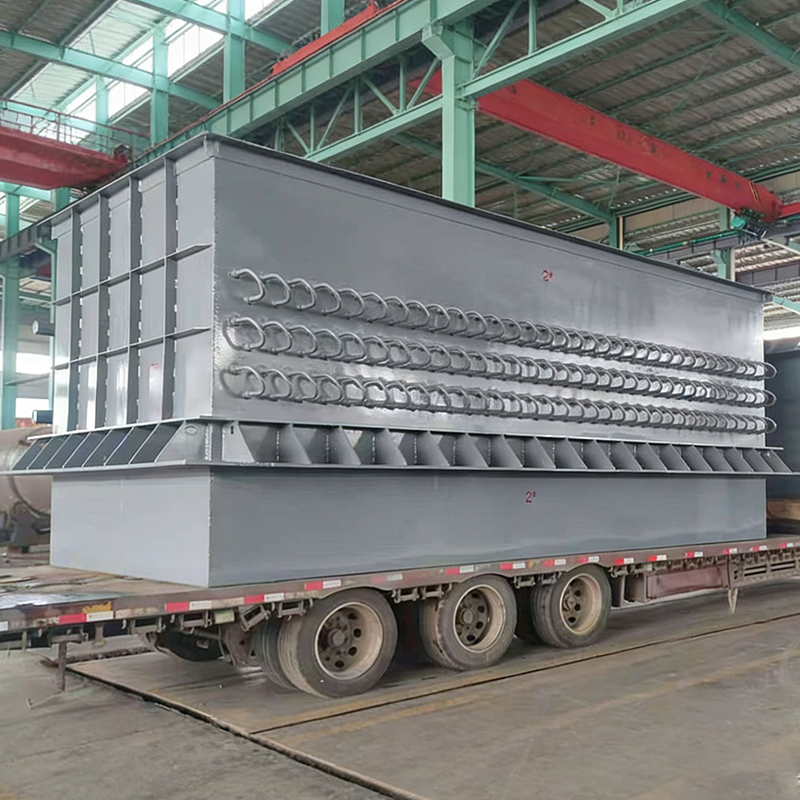
 Coke Oven Flue Gas Waste Heat Boiler for Medium-Low Temperature RecoveryThis boiler recovers heat from 260-300°C coke oven flue gas to produce steam, reducing outlet temperature to 140-160°C. Its relief valve sizing must account for transient heat input, making it relevant when investigating overpressure events.View Product →
Understanding why a boiler pressure relief valve opens is just as important as knowing how to reset it. In our engineering review of troubleshooting reports from industrial steam plants, certain causes appear far more often than others. The chart below summarizes a field-based sample of 180 unplanned relief valve discharge events collected by plant maintenance teams and supplier engineers. The cause grouping is practical, not academic, and it helps plant teams decide where to spend inspection time. Read the length of each bar as the percentage of recorded events attributed to that cause.
Common causes of industrial boiler pressure relief valve discharge
The first finding is that overfiring appears as the leading trigger in this sample. A failed burner controller, an incorrectly calibrated fuel valve, or an interrupted flame signal can add heat faster than the boiler can convert water to steam. The relief valve then becomes the only component that prevents a pressure excursion. The second-largest cause, a closed or restricted steam outlet valve, is often avoidable through simple operating rules. Many plants isolate steam lines for maintenance and then forget that a block valve remains shut. Failed pressure sensors and controls form the third group, confirming the value of regular calibration. In these cases the set point was not the issue; the system simply never received the correct signal to reduce firing. Thermal expansion explains the events in hot water systems where an expansion tank is undersized or isolated by a shut-off valve. Mechanical wear and setpoint drift account for a smaller but still significant share, and they usually show up during startup testing. Water hammer, the smallest group, is rare but dangerous because it creates a sudden pressure transient. It often results from rapid changes in steam demand, poor condensate drainage, or quick valve movement. Overall, the lesson is that a boiler pressure relief valve rarely protects against a problem that appears without earlier warnings.
Selection should begin with the boiler MAWP and the certified relief capacity, not with an existing valve size. When the wrong valve is installed, the boiler can pass an inspection only if the nameplate, capacity, and set pressure match the design calculations. The valve must also fit the available inlet connection, discharge piping layout, and operating temperature range.
Use these selection factors as a starting point:
| Selection factor | Decision impact | Common pitfall |
|---|---|---|
| Set pressure vs. MAWP | Defines when the valve opens | Setting too high to prevent nuisance discharge |
| Certified capacity | Ensures full flow under worst-case heat input | Copying the boiler nameplate without checking capacity |
| Valve materials | Withstands steam, condensate, and process contaminants | Choosing a high-temperature alloy when a carbon steel body is appropriate |
| Inlet piping arrangement | Limits pressure loss and chatter | Adding length and elbows to reach a convenient discharge location |
| Backpressure | Affects opening and capacity | Connecting multiple valves to one undersized drain header |
For waste heat boilers, the capacity calculation must include the maximum possible steam generation at maximum flue gas flow, high flue gas temperature, and worst-case process conditions. A manufacturer that quotes a waste heat recovery unit without a relief valve sizing calculation is leaving too much to guesswork.
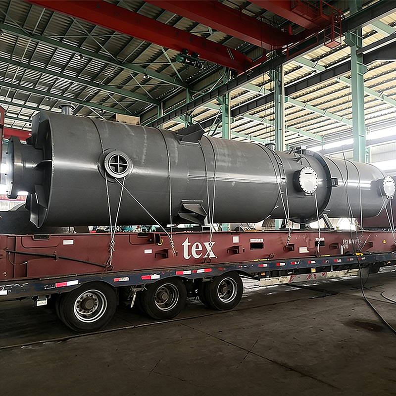 High-Temperature Flue Gas Waste Heat Recovery Unit for Oxygen-Blown GasifierThis unit handles flue gas above 800°C using high-temperature alloys and dust-resistant designs. Since its relief valve capacity must be calculated for worst-case conditions, it is important to verify ASME certification and set pressure documentation.View Product →
When you source valves from a wholesaler or a third-party distributor, insist on an ASME-certified capacity nameplate and clear documentation of the set pressure. The extra paperwork is not bureaucracy; it is the only way to verify that the valve will perform during an overpressure event.
Correct installation makes the difference between a relief valve that protects on every demand and one that fails during an emergency. The valve must be mounted vertically, close to the boiler steam drum, with a full-size inlet and no intervening stop valve unless the jurisdiction allows it. Outlet piping should be self-draining and must not create excessive backpressure.
Manual lever testing of a boiler pressure relief valve should be approached carefully. A lever test proves that the valve mechanism can be lifted, but it does not prove that the valve will open at the correct set point. On old valves, a manual test can push scale and debris into the seat, causing a leak that did not exist before. After years of service, the safer route is often to remove the valve and perform a bench test.
| Frequency | Task | Purpose |
|---|---|---|
| Before each startup | Confirm the outlet line is not blocked and the valve mechanism is free | Prevent simple line obstructions |
| Monthly or quarterly | Perform a careful lever test at service pressure, if the code allows | Check disc movement and seat condition |
| Annually | Bench test the valve for set pressure, blowdown, and capacity | Verify the valve still meets the nameplate rating |
| After a discharge event | Inspect the seating surface and replace damaged parts | Prevent gradual leakage |
| After a water treatment upset | Look for scale, corrosion, or oil carryover on the disc | Catch contamination before it affects seating |
Do not adjust a valve set point without reviewing the design calculation and the boiler data report. In many jurisdictions, changing the set pressure requires a new capacity certification and an inspection. The maintenance team should also record every service date, test result, and replacement part, because that history becomes the evidence that the boiler is safe to operate.
Experienced manufacturers treat boiler pressure relief as part of the overall boiler thermal-hydraulic design, not as a purchasing accessory. In our own engineering process, the steam drum MAWP, the safety valve set point, and the downstream steam pressure control are reviewed together. This matters most in waste heat recovery, where the heat source is not as stable as a fuel-fired boiler.
For a sintering circular cooler, for example, the exhaust air temperature and volume change with material bed depth, cooling air flow, and production rate. The relief valve must be sized for the worst-case steam flow, not the average production curve. A supplier that understands these process fluctuations will also verify the response time, the blowdown setting, and the effect of long flue gas ducts on pressure transients.
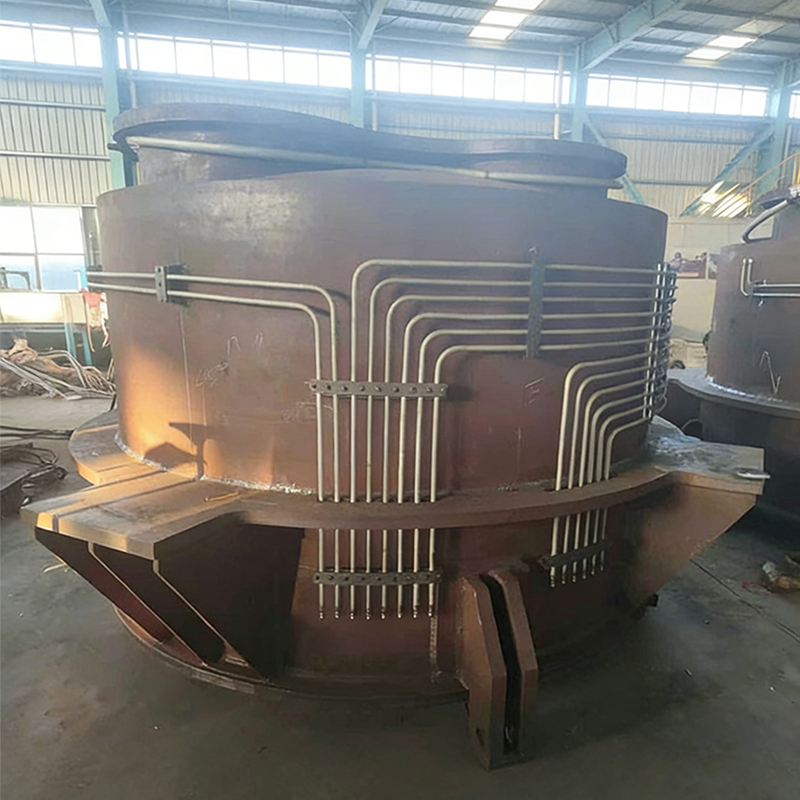 Sinter Circular Cooler Waste Heat Boiler with Steam GenerationThis boiler recovers waste heat from about 400°C sintering exhaust gas to generate steam, using circular cooling and high-temperature resistant materials. Its relief valve sizing should consider variable exhaust conditions and discharge path design.View Product →
In high-temperature processes such as oxygen-blown converters or coke oven flue gas systems, the design must include the relief line discharge path, whether the steam is vented to atmosphere or routed to a deaerator. The manufacturer should provide a full system description, including the valve certificate, installation drawing, and recommended spares. When you compare bids from boiler manufacturers and heat recovery equipment suppliers, ask each one how the relief valve capacity was calculated. If the answer is simply that it was copied from a similar project, treat that as a risk. A responsible supplier will walk you through the maximum heat input case, the MAWP, and the allowable overpressure.
Boiler pressure relief is a code-driven subject, and the requirements can vary by jurisdiction, boiler type, and pressure class. The links below connect to background material on industrial waste heat systems and on the quality process used by our manufacturing facility.
Before changing a valve setting, always review the original design document, the boiler data report, and the applicable local regulation. A relief valve that opens earlier than necessary wastes energy, but one that opens too late is a serious safety hazard.
We will help you move towards success.

Maqiao North High tech Industrial Agglomeration Zone, Jingjiang City, Taizhou City, Jiangsu Province

+86-18752676699 / +86-13961025664
 Previous